A downstream tangential flow filtration step that behaved beautifully at 30 mL has no obligation to behave at 2 L. Anyone who has watched a validated bench process suddenly gain aggregate, drop yield, or shift potency the first time it ran at scale knows the feeling.
The investigation that follows rounds up the usual suspects. The cell line. The resin. The buffer lot. The membrane. Almost never the plumbing that connects them.
Which is a shame, because the plumbing is often the one that did it.
The part of the process that quietly changed
Scale-up is meant to be an exercise in keeping things the same. You hold the membrane chemistry, the pore size, the normalized flux in LMH, and the wall shear rate inside the fiber or channel. Do that and, on paper, performance should travel with you from bench to clinical to commercial.
In practice, one thing refuses to stay constant: the loop the product actually travels through. Bigger volumes bring longer tubing, wider bores, more connectors, more hold-up, and a larger pump running at a different point on its curve. The filter is identical. The road to it is not.
The overlooked variable finally has a citation
For years this was folklore, the sort of thing a gray-haired process engineer muttered after a bad campaign. It is now in the peer-reviewed literature. A 2026 workflow for scaling TFF said it without hedging: filter selection receives significant attention, while the design of the hydraulic loop has emerged as a blind spot in implementation.
That study is upstream, perfusion cell retention, not the downstream concentration and diafiltration where fragile modalities are finished. The principle crosses over intact, and if anything it bites harder downstream, because the product is already made and every unit lost is irreplaceable. Its most useful line is the quiet one: hydrodynamic conditions can be compared across processes and scales, whereas fouling is proprietary and messy. The hydraulics are just physics, and physics is knowable.
Which means the trial-and-error most teams still use to scale a loop is a choice, not a law of nature.
Why the loop won't scale on a spreadsheet
Multiply the flow rate by a number and the loop's behavior stubbornly refuses to multiply by the same number. Several things move at once, and they pull against each other.
| Loop mechanism | What happens as you scale |
|---|---|
| Hydraulic load | Pressure drop rises steeply with flow and length, and inversely with roughly the fifth power of the bore diameter. A modest tubing choice swings the pump speed, and the shear, hard. |
| Shear dose | A TFF step recirculates the batch hundreds of times. A bigger pump on a heavier loop delivers more shear per pass, and the quantity that damages product is the dose: shear per pass multiplied by the number of passes. |
| Suction-side cavitation | Longer, narrower suction lines and a larger pump lower the inlet pressure. Cavitation onset shifts, and every vapor collapse is a localized, product-destroying energy spike right at the product. |
| Hold-up volume | Dead volume in tubing, connectors, and pump heads grows with the system but not with the value of the product. For a small, high-value batch, that unrecoverable volume is direct yield loss. |
| TMP stability | Pressure control and pulsation behave differently on a larger loop. Swings in transmembrane pressure drive fouling and flux decline that never showed up at bench. |
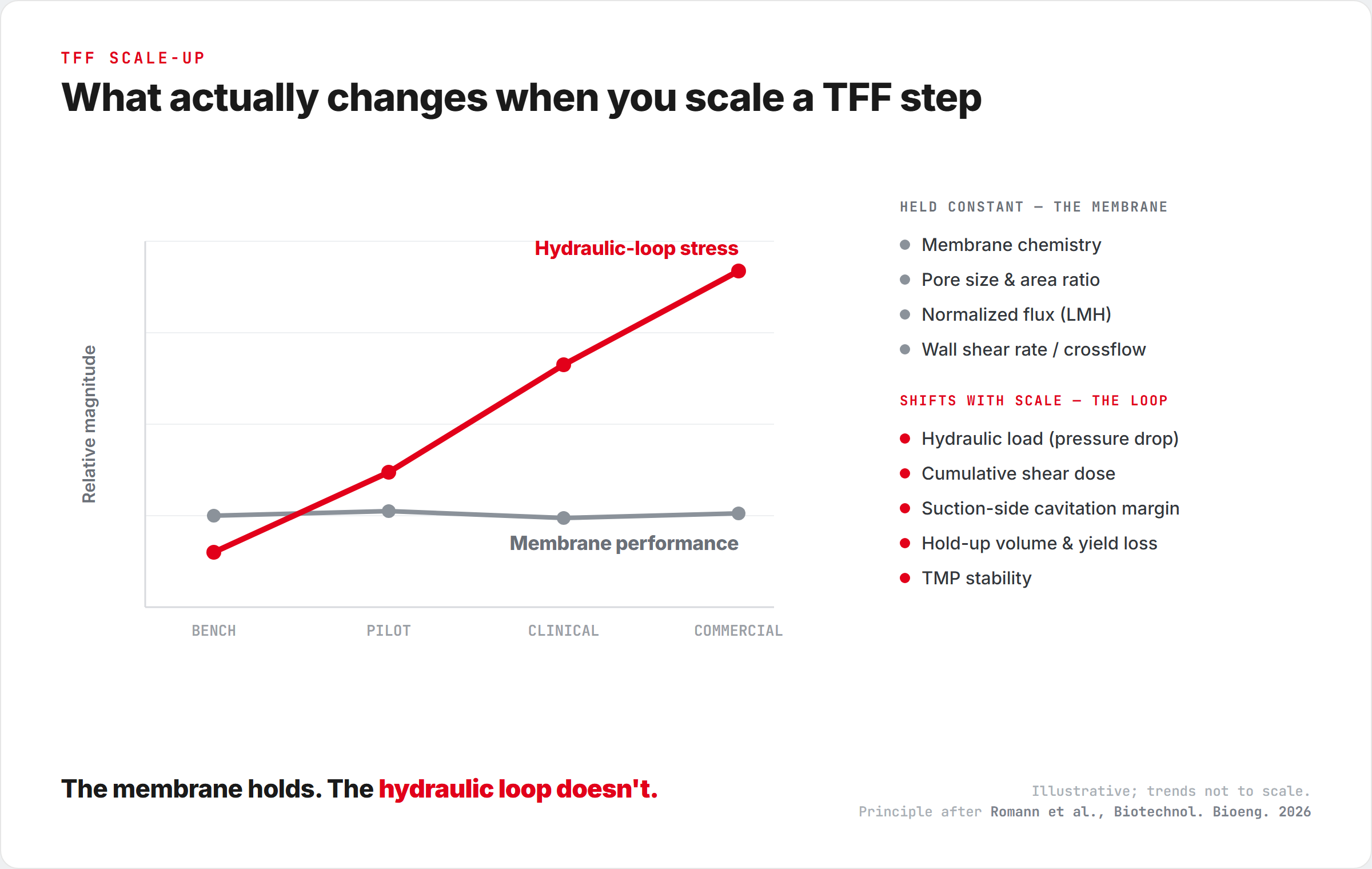
None of these is exotic. Every one is calculable from tube geometry, flow rate, and fluid properties. They are simply calculated far less often than a membrane is selected.
Keep it constant, or characterize it. Don't guess.
The fix is not heroic. It is a discipline: decide what you pin across scales, and measure the rest rather than hope it followed you.
| Hold constant across scales | Characterize at every scale |
|---|---|
| Membrane chemistry, pore size, area ratio | Overall hydraulic load of the loop |
| Normalized flux (LMH) | Cumulative shear dose (pump plus number of passes) |
| Wall shear rate / crossflow | Cavitation margin on the suction side |
| Feed conditioning and control strategy | Hold-up volume, its yield cost, and TMP stability |
The 2026 workflow formalizes this into a four-step sequence, process scaling, filter scaling, hydraulic loop design, and pump selection, precisely so the loop stops being the component nobody sized. Whatever framework you adopt, the principle is the same: give the loop the rigor you already give the membrane.
The membrane is half the decision. The half almost nobody sizes is the other half, and it is the half that tends to decide what happens the day you leave the bench.
Where Alphinity fits
This is the argument the TFFi™ platform was built around. The same fluid path, the same ultra-low-shear PIXER® pump, and the same control system run at every scale, so the hydraulic loop is not reinvented between bench and clinical. The physics you characterize at small scale is the physics you run at large scale, which leaves far less to reverse-engineer after a surprising batch.
Common questions
Why does my TFF process fail when I scale it up?
Usually because the hydraulic loop changed while the membrane did not. At scale the loop has longer tubing, wider bores, more connectors, more hold-up volume, and a larger pump running harder. The cumulative shear dose, the cavitation margin, and transmembrane pressure stability all shift, so a process validated at bench meets different mechanical conditions at scale.
Is it the membrane or the equipment that limits TFF scale-up?
The membrane usually scales cleanly because chemistry, pore size, and normalized flux are held constant. The equipment around it, the tubing, connectors, and pump that make up the hydraulic loop, is what most often changes and causes yield or quality loss at scale.
Does tubing and loop design really affect TFF performance?
Yes. Pressure drop scales inversely with roughly the fifth power of tube diameter, so small bore choices swing the required pump speed and the shear it delivers. Hold-up volume in tubing, connectors, and pump heads is direct product loss, and the pump's operating point sets the shear delivered on every recirculation pass.
What is Starling flow?
In hollow-fiber modules, common in perfusion and cell retention, Starling flow is the internal recirculation of filtrate along the fiber driven by the axial pressure drop in the lumen. It is much less of a factor in flat-sheet UF and DF, but it is a clear example of how loop and module geometry can change filtration behavior when you scale.
What should stay constant when scaling a TFF process?
Hold the membrane chemistry, pore size, and area ratio constant, keep the normalized flux (LMH) constant, and keep the wall shear rate (crossflow) constant. Then characterize the rest, hydraulic load, cumulative shear dose, cavitation margin, hold-up volume, and TMP stability, at each scale rather than assuming it transfers.
Romann P, Lee K, Natarajan V, et al. A General Workflow for Tangential Flow Filtration Perfusion Scale-Up. Biotechnology and Bioengineering, 2026. Open access. doi:10.1002/bit.70335. Upstream in focus, but the loop-design principle carries directly to downstream UF and DF.
What to read next
Where the mechanical damage comes from, and why recirculation multiplies it.
Why the suction side of the pump is where fragile product quietly disappears.